How to Choose Low Carbon Steel Grating for Global Projects?
Choosing Low Carbon Steel Grating for global projects requires more than comparing purchase prices. The specification must connect carbon performance, structural safety, corrosion resistance, and local supply conditions. According to worldsteel’s World Steel in Figures 2024, global crude steel production reached approximately 1.89 billion tonnes in 2023. That scale shows why small material decisions can influence major infrastructure footprints.
The IEA’s Iron and Steel Technology Roadmap identifies steelmaking as responsible for roughly 7–9% of global carbon dioxide emissions. Therefore, buyers should request verified environmental data, recycled-content details, production routes, and product-specific Environmental Product Declarations where available. ISO 14025 and EN 15804 provide useful frameworks for checking such declarations. However, carbon claims should never replace engineering evidence. A grating panel supporting maintenance workers still needs suitable load ratings, bearing-bar dimensions, weld quality, and slip resistance.
Details matter. A coastal platform may require hot-dip galvanizing, while an inland factory may prioritize abrasion resistance and rapid delivery. Confirm steel grades, surface treatment, panel tolerances, packaging, and mill traceability before approving drawings. The World Steel Association also emphasizes efficiency and emissions reduction across steel production, but performance data can vary between suppliers.
A perfect decision is unlikely. Transport distance may reduce one benefit while improving another. A cheaper grating can create higher replacement emissions later. This guide examines practical selection methods, supplier verification, documentation, and lifecycle trade-offs. The strongest choice is not always the lowest-carbon option on paper. It is the option that remains safe, durable, traceable, and credible in real project conditions.
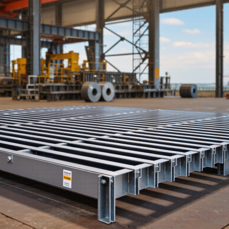
Define Project Loads and Spans Using Grating Load Tables and Deflection Limits
For global projects, low-carbon steel grating should be selected from verified load data, not appearance. Start by defining the actual load case: pedestrian traffic, maintenance carts, stored materials, or equipment wheels. Record both uniform load and concentrated load. Then measure the clear span between supports. Do not assume the nominal panel length equals the structural span. That small error can change the required bearing bars. Use the governing design standard and project safety factors. Requirements vary by country and application. Do not guess.
Read the grating load table at the intended bearing-bar size, spacing, and span. Tables usually show allowable loads and deflection, but their assumptions must be checked. A panel may carry the load yet feel flexible underfoot. Set a project deflection limit, such as span divided by 200, only when the specification permits it. Some floors require stricter limits because vibration, drainage, or equipment alignment matters. Check wheel loads separately. They are not simply heavier uniform loads.
During review, mark every support line on the plan and compare it with the table’s tested orientation. Bearing bars must cross the span; cross bars do not replace them. Include opening sizes, kick plates, removable panels, and edge angles. For outdoor work, drainage and coating durability also affect long-term performance. One practical caution: a conservative table choice can still fail if supports twist or welds are incomplete. Inspect the steel, dimensions, welds, and bearing length before installation. Recheck calculations when site conditions change. They often do.
How to Choose Low Carbon Steel Grating for Global Projects? - Define Project Loads and Spans Using Grating Load Tables and Deflection Limits
Indicative preliminary selection table for welded low carbon steel grating. Values are shown in metric units and should be checked against the applicable project design code, support conditions, opening requirements, corrosion allowance, and manufacturer-certified load tables.
| Reference |
Bearing Bar Size
(Depth × Thickness) |
Bearing Bar Pitch
(mm) |
Clear Span
(mm) |
Indicative Service UDL
(kN/m²) |
Deflection Limit |
Calculated Deflection at Listed UDL
(mm) |
Governing Check |
Typical Preliminary Use |
| LG-01 |
30 × 3 mm |
100 |
600 |
20.0 |
L/240 = 2.5 mm |
2.5 |
Deflection |
Short-span walkways and platforms |
| LG-02 |
30 × 3 mm |
100 |
900 |
5.9 |
L/240 = 3.8 mm |
3.8 |
Deflection |
Light-duty access platforms |
| LG-03 |
30 × 5 mm |
100 |
1,200 |
4.2 |
L/240 = 5.0 mm |
5.0 |
Deflection |
General industrial walkways |
| LG-04 |
40 × 5 mm |
100 |
1,500 |
11.8 |
L/240 = 6.3 mm |
4.6 |
Bar strength |
Medium-duty platforms and maintenance areas |
| LG-05 |
40 × 6 mm |
100 |
1,800 |
9.9 |
L/240 = 7.5 mm |
5.0 |
Bar strength |
Longer-span plant access platforms |
| LG-06 |
50 × 5 mm |
100 |
1,800 |
10.7 |
L/240 = 7.5 mm |
7.5 |
Deflection |
Heavy-duty walkway applications |
| LG-07 |
50 × 6 mm |
100 |
2,000 |
10.0 |
L/240 = 8.3 mm |
8.3 |
Deflection |
Heavy-duty platforms with wider support spacing |
| LG-08 |
60 × 6 mm |
100 |
2,400 |
9.1 |
L/240 = 10.0 mm |
10.0 |
Deflection |
Extended-span industrial access areas |
Engineering basis:
Indicative values assume simply supported grating panels, bearing bars spanning in one direction, uniformly distributed loading, a 100 mm bearing-bar pitch, elastic modulus of approximately 200 GPa, and low carbon steel with a nominal yield strength of approximately 250 MPa. The table uses an L/240 serviceability limit as a screening criterion. Concentrated wheel loads, maintenance loads, impact loads, seismic effects, vibration, local plate bending, support detailing, and corrosion loss require separate verification.
Selection method:
Confirm the design uniform load in kN/m², identify the clear bearing span, select a bearing-bar size with a listed capacity above the project demand, and verify that the calculated deflection does not exceed the specified limit. For vehicle or trolley traffic, use a certified concentrated-load table rather than relying only on the uniform-load values shown above.
Compare ASTM A36 at 250 MPa Yield Strength with S235JR at 235 MPa
How to Choose Low Carbon Steel Grating for Global Projects?
When comparing ASTM A36 with S235JR, the yield-strength difference looks small. ASTM A36 typically provides 250 MPa, while S235JR provides 235 MPa for thinner sections. That difference is about six percent. However, S235JR strength can reduce as material thickness increases. Therefore, thickness must appear clearly on the mill certificate. Do not compare grade names alone.
A grating designer should check bearing-bar size, span, spacing, and applied loads. A walkway carrying pedestrians differs greatly from one carrying pallet trucks. For example, closely spaced bars may improve comfort, while deeper bars usually improve stiffness.
Yield strength controls permanent deformation, but deflection can still govern the design. A stronger steel does not automatically create a safer platform.
Field inspections should also consider weld quality, cut edges, drainage, and standing water. Rust often starts around damaged coatings and trapped dirt. ASTM A36 may suit many general structural applications, while S235JR can be appropriate when European documentation and impact requirements are specified. The “JR” designation indicates impact testing at 20°C, but the complete certificate still matters. Ask for heat numbers, chemical results, mechanical tests, and dimensional records.
A simple strength ranking can mislead.
I have seen project teams select steel first and calculate loads later. That order creates rework. Climate, transport rules, fabrication equipment, and local design codes may change the better choice. Even a small mismatch between the drawing and delivered thickness deserves review.
Select Bearing-Bar Sizes by Span, Load Class, and Safety Factors
For global projects, bearing-bar selection starts with the clear span, not the panel’s appearance. Measure the unsupported distance between beams, then identify the governing load class. EN 1991-1-1 lists imposed floor loads commonly ranging from 2.0 to 7.5 kN/m², depending on occupancy and crowd conditions. National annexes may change these values. Check them.
A longer span requires deeper bearing bars, closer spacing, or stronger supports. NAAMM MBG 531 load tables show how bar depth and thickness affect capacity, deflection, and walking comfort. A 30 × 3 mm bar may suit a short pedestrian span, but it cannot be approved by size alone. Service deflection matters. Many project specifications use L/200 or a 6 mm limit, but these limits are not universal.
Use factored loads, not hopeful estimates. EN 1990 separates variable actions, permanent actions, and partial safety factors; the governing combination depends on the design code. Include concentrated wheel loads, maintenance carts, impact, corrosion loss, and openings for toes or tools. ISO 2394 also emphasizes reliability-based safety decisions. A neat spreadsheet is not proof. Small assumptions become expensive mistakes. Recheck the bearing direction, weld quality, and actual support length before fabrication. Low-carbon steel can meet the structural need, but its declared grade, coating system, and inspection records must remain traceable across borders.
How to Choose Low Carbon Steel Grating for Global Projects?
Select Bearing-Bar Sizes by Span, Load Class, and Safety Factors
Indicative maximum clear spans for commonly specified welded steel grating bearing bars under uniformly distributed service loads.
The screening values assume a 1.5 load factor and a deflection limit of approximately span/200. Final selection must be verified against the applicable project code, support conditions, concentrated loads, corrosion allowance, and fabrication tables.
Choose ISO 1461 Galvanizing with 85 μm Average Coating Above 6 mm
For global projects, low carbon steel grating must match both loading needs and exposure conditions.
Hot-dip galvanizing under ISO 1461 is a practical specification for outdoor platforms, walkways, and drainage covers. For steel thicker than 6 mm, ISO 1461 requires an average zinc coating thickness of 85 μm, with a local minimum of 70 μm. This distinction matters. A single measurement cannot represent the whole grating.
The NACE IMPACT study estimated global corrosion costs at about US$2.5 trillion annually, equal to roughly 3.4% of global gross domestic product. Galvanizing does not remove every corrosion risk, but it creates a durable barrier and sacrificial protection. Specify coating inspection after fabrication, especially around welds, cut edges, bearing bars, and difficult-to-drain sections. Drainage holes should remain open. Trapped water quietly defeats good engineering.
A project specification should state “ISO 1461, average coating thickness 85 μm for steel above 6 mm.” It should also require certified thickness records and visual checks before shipment. In site work, damaged lifting points are easy to overlook. Repair procedures must follow the applicable galvanizing standard. The choice is strong, but not perfect. Severe marine exposure, abrasion, or chemical contact may require additional design review. Sometimes, the drawing looks complete while the inspection plan remains vague. That is a costly weakness.